Key Takeaways
- A residential ESS is far more than a battery — it is a complete energy ecosystem where architecture determines real-world performance
- Four architecture types exist (DC-coupled, AC-coupled, hybrid, off-grid), each optimized for different scenarios
- BMS and EMS form the invisible backbone that protects hardware and maximizes ROI
- Modular, stackable LiFePO4 batteries — certified to CE and IEC 62619 — deliver the safest, most scalable foundation
- Choosing the right architecture today prevents costly redesigns tomorrow
The global residential energy storage market surpassed 42 GWh of installed capacity in 2024. In Europe alone, Germany leads with over 1.5 million home battery systems installed, while Poland’s Mój Prąd program has driven a 340% year-over-year growth in residential storage adoption[Fraunhofer ISE]
The European Commission’s REPowerEU initiative has set ambitious targets for energy independence, positioning residential storage as a cornerstone of the EU’s 2030 energy strategy ([European Commission]).
That knowledge gap carries real consequences. Choose the wrong architecture and you could lose 10 to 25 percent of your solar energy to unnecessary conversions. Choose a non-expandable configuration and you may face a full system replacement when your needs grow. Choose components that cannot communicate with each other and you risk nuisance shutdowns that leave you without backup power exactly when you need it most.
This guide exists to close that gap.
We will walk through every layer of a residential ESS — from the physical components on your wall to the invisible software logic that decides when electrons flow and where. We will compare all four architecture types side by side, then hand you a decision framework so you can match the right topology to your home, your budget, and your future plans.
Throughout the guide you will see references to real-world applications built on EWAY Energy’s LiFePO4 battery platform. Our modules carry CE marking and are fully certified to IEC 62619 — the international standard that tests lithium batteries against short circuits, overcharging, thermal abuse, and mechanical shock. Where relevant, we will explain exactly what those certifications mean for your safety and peace of mind.
If at any point you want to dive deeper into a specific sub-topic — AC versus DC coupling, wiring diagrams, or battery sizing — you will find dedicated links to our companion articles. Think of this page as the map. The linked guides are the street-level tours.
Let’s start with the foundation.
What Is a Residential Energy Storage System?
A Complete Energy Ecosystem, Not Just a Battery
When most people hear “home battery,” they picture a single box mounted on a garage wall. In reality, a residential Energy Storage System is an integrated ecosystem that generates, stores, converts, manages, and distributes electricity across your home and — in many cases — back to the grid.
A useful analogy: think of a municipal water system. The reservoir stores water, but without pumps, treatment plants, pressure regulators, and smart valves, the water never reaches your tap at the right pressure and quality. An ESS works the same way. The battery is the reservoir. Everything around it — inverters, management systems, switches, meters — ensures that energy arrives at each appliance at the right voltage, the right time, and the lowest possible cost.
A well-designed residential ESS serves three primary functions:
- Solar self-consumption maximization. Instead of exporting cheap surplus solar energy to the grid and buying expensive power back at night, the battery stores midday excess and releases it after sunset. In most markets, this alone can cut electricity bills by 40 to 70 percent.
- Backup power during outages. When the grid fails, an automatic transfer switch isolates your home and the battery takes over — typically within 10 to 20 milliseconds. Critical loads such as refrigerators, lighting, internet routers, and medical equipment continue to operate without interruption.
- Time-of-use arbitrage. Utilities in California, Germany, Australia, and many other regions charge significantly more during peak evening hours. An ESS can charge from the grid (or solar) when rates are low and discharge when rates are high, turning your battery into a financial instrument.
Emerging capabilities are expanding this list. Peak shaving reduces demand charges for homes with high intermittent loads such as EV chargers. Demand response programs pay homeowners to discharge batteries during grid stress events. Vehicle-to-home (V2H) integration is on the horizon, allowing an electric car to serve as an additional storage module.
All of these capabilities, however, depend on one critical decision that must be made before a single bracket is screwed into the wall: the system architecture.
Why Architecture Matters More Than Battery Specs
Open any solar forum and you will find homeowners debating kilowatt-hours, cycle life, and price per kWh. Those specifications matter. But they are secondary to architecture — the way every component connects, communicates, and cooperates.
Consider three real-world scenarios:
Scenario 1 — Efficiency loss from wrong coupling. A homeowner installs a 10 kWh battery in an AC-coupled configuration where a DC-coupled option was available. Solar energy now travels through two extra conversion stages — DC to AC, then AC back to DC for storage. Each conversion loses 3 to 5 percent. Over a year, that architecture decision alone wastes 300 to 500 kWh — enough to power a refrigerator for four months.
Scenario 2 — Expansion blocked by architecture. Another homeowner buys a string inverter and a single battery. Two years later, they purchase an electric vehicle and need double the storage. But the string inverter has no battery input. The only option is to replace the inverter entirely — a cost that could have been avoided by choosing a hybrid inverter from the start.
Scenario 3 — Architecture done right. A third homeowner selects a hybrid inverter, a modular stackable battery with CAN Bus communication, and an EMS that supports time-of-use scheduling. Three years later, they add two more battery modules and a second PV string. No inverter replacement. No rewiring. The system scales smoothly because the architecture was designed for growth.
The lesson is clear: architecture is the envelope within which every future upgrade must fit. Get it right on day one and every subsequent decision becomes easier, cheaper, and more efficient.
In the sections that follow, we will first examine each component individually, then show how they connect in four distinct architecture topologies, and finally give you the tools to choose, size, and implement the right one.
Key Components of a Residential ESS Architecture
Before we can discuss how components connect, we need to understand what each one does and why it matters. Think of this section as the parts list for a complex machine. In the next section, we will assemble those parts into four different machines.
Solar PV Array — The Energy Source
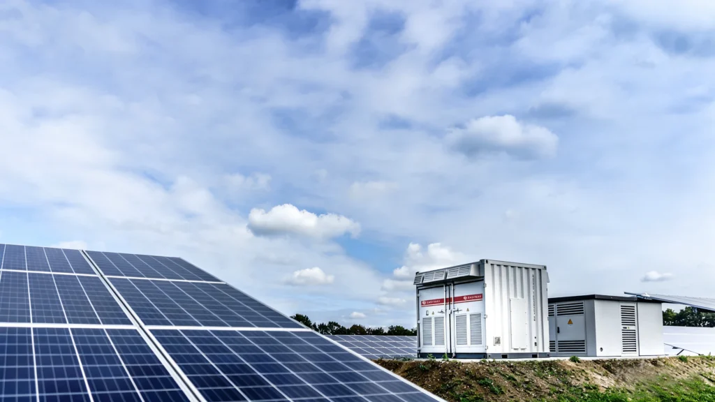
Everything begins on the roof — or the ground-mount rack, or the carport canopy. Photovoltaic panels convert sunlight into direct current (DC) electricity. Two characteristics of that DC output directly influence architecture choices downstream:
- Voltage range. A string of panels might produce 150 to 600 volts DC depending on the number of panels wired in series. This voltage must fall within the operating window of whichever device receives it first — be that a string inverter, a charge controller, or a hybrid inverter’s MPPT input.
- Power variability. Cloud cover, shading, and seasonal tilt angles cause PV output to fluctuate minute by minute. The system architecture must handle these swings gracefully.
The critical takeaway: PV output is always DC. How that DC energy reaches your battery and your appliances — and how many conversion steps it passes through along the way — is the essence of architecture design.
Inverter Types and Their Role in Architecture
If the PV array is the source and the battery is the reservoir, the inverter is the translator. It converts DC to AC (or vice versa) and, in many architectures, also controls the battery charge and discharge process. The type of inverter you choose effectively locks you into an architecture path.
| Inverter Type | What It Does | Architecture Implication |
|---|---|---|
| String Inverter | Converts PV DC → AC. No battery port. | Forces AC-coupled architecture if you add a battery later |
| Microinverter | Same as string inverter but per-panel. No battery port. | Forces AC-coupled architecture |
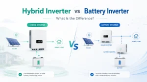
| Hybrid Inverter | Converts PV DC → AC and manages battery DC charge/discharge via built-in MPPT and battery port | Enables DC-coupled or hybrid architecture natively |
Hybrid inverters deserve special attention. A single hybrid inverter replaces what would otherwise require two separate boxes — a PV inverter and a battery inverter. This consolidation reduces cost, wiring complexity, and conversion losses. It also provides a natural expansion path: most hybrid inverters accept multiple MPPT inputs and one or two battery channels, allowing you to add PV strings or battery modules later without replacing the inverter itself.
Battery Pack — LiFePO4 as the Architecture Foundation
The battery stores energy and releases it on demand. Three lithium chemistries dominate the residential market:
| Chemistry | Cycle Life | Thermal Runaway Onset | Energy Density | Cost Trend |
|---|---|---|---|---|
| LiFePO4 (LFP) | 6,000+ cycles | ~270 °C | Moderate | Falling fast |
| NMC | 3,000–4,000 cycles | ~210 °C | High | Stable |
| LTO | 10,000+ cycles | Very high | Low | High |
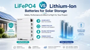
LiFePO4 has become the dominant chemistry for residential storage — and for good reason. Its thermal runaway threshold sits 60 degrees Celsius above NMC, making it inherently safer for indoor installation. Its cycle life often exceeds 6,000 full cycles at 90 percent depth of discharge, translating to 15 or more years of daily use. And as global LFP production scales, costs are dropping toward $80 to $100 per kWh at the cell level.
EASYWAY residential battery modules use automotive-grade LiFePO4 cells and have passed the full IEC 62619 safety test suite — including external short circuit, overcharge and mechanical shock. Each module also carries CE marking covering the Low Voltage Directive and Electromagnetic Compatibility Directive for the European market, plus UN 38.3 transportation certification.
One architectural consideration unique to batteries: series versus parallel configuration. Connecting modules in series increases system voltage (e.g., two 48 V modules in series yield 96 V). Connecting in parallel increases capacity while maintaining voltage (e.g., two 10 kWh modules in parallel yield 20 kWh at 48 V). Most residential systems today operate on a 48-volt platform with modules connected in parallel for easy expansion — a design philosophy that EASYWAY energy storage system follows natively.
Battery Management System — The Guardian
Every lithium battery requires a BMS. Without it, cells can overcharge, over-discharge, overheat, or drift out of balance — any of which can degrade performance or, in extreme cases, create a safety event.
A well-designed BMS performs five continuous tasks:
- Cell voltage monitoring and balancing. Individual cells within a module inevitably diverge over time. The BMS detects imbalances and redistributes charge — either passively (dissipating excess as heat) or actively (transferring charge between cells). Active balancing, which EWAY BMS units use, is faster and wastes less energy.
- Overcharge and over-discharge protection. The BMS disconnects the battery if any cell exceeds 3.65 V (for LFP) or drops below 2.5 V, preventing permanent capacity loss.
- Thermal management. Temperature sensors throughout the pack trigger charge rate reduction or full disconnection if temperatures exceed safe thresholds — typically 55 °C for charging and 60 °C for discharging.
- Short circuit and overcurrent protection. High-speed contactors or MOSFETs open the circuit within microseconds if current spikes above rated limits.
- State estimation and reporting. The BMS calculates State of Charge (SOC) and State of Health (SOH) and transmits this data to the inverter via a communication bus — enabling the EMS to make intelligent dispatch decisions.
A critical point often overlooked: the BMS is not just a safety device — it is an architecture node. It speaks to the inverter through CAN Bus or RS485 (Modbus RTU). If the BMS and inverter cannot communicate — due to protocol mismatch, incorrect baud rate settings, or poor cable shielding — the entire system may shut down. We address communication troubleshooting in detail later in this guide.
Energy Management System — The Strategist
If the BMS is the guardian of the battery, the EMS is the strategist of the entire system. It sits above the BMS in the control hierarchy, ingesting data from multiple sources and making real-time decisions about energy flow.
An EMS typically receives input from:
- The PV inverter (current solar production in watts)
- The smart meter or CT clamp (current home consumption and grid import/export)
- The BMS (battery SOC, available charge/discharge power, temperature)
- An external data feed (utility TOU rate schedule, weather forecast)
Based on these inputs, the EMS executes a dispatch strategy. A simplified logic might look like this:
IF solar_production > home_load THEN
    → Charge battery with surplus
    IF battery_SOC = 100% THEN
        → Export surplus to grid
ELIF electricity_price = PEAK THEN
    → Discharge battery to home load
ELIF electricity_price = OFF_PEAK AND battery_SOC < 20% THEN
    → Charge battery from grid
ELSE
    → Hold battery, power home from grid
In practice, modern EMS platforms add layers of sophistication. Some integrate weather forecasts to pre-charge the battery before a cloudy period. Others learn household consumption patterns over weeks and months, shifting charge windows to align with predicted demand. AI-powered EMS — still emerging but gaining traction — can optimize across multiple variables simultaneously, including dynamic electricity pricing, EV charging schedules, and heat pump operation.
The EMS is typically embedded within the hybrid inverter’s firmware or runs on a standalone gateway device. For homeowners, the EMS is often the “app on the phone” — the dashboard that shows real-time energy flows, historical savings, and system alerts.
Looking ahead to 2025 and beyond, EMS intelligence will become the primary differentiator between commodity storage systems and high-performance ones. The hardware is converging; the software is diverging.
Transfer Switch, Metering, and Balance of System
Three final components complete the architecture:
Automatic Transfer Switch (ATS). When grid voltage drops to zero, the ATS disconnects your home from the grid and simultaneously connects it to the inverter’s backup output. This happens in 10 to 20 milliseconds — fast enough that most electronics never notice the transition. The ATS also prevents “islanding,” a dangerous condition where your system would feed power back into a supposedly dead grid, potentially electrocuting utility workers.
Metering. Current transformers (CTs) clamped around your main feed cables measure real-time import and export power. This data feeds the EMS. Without accurate metering, the EMS flies blind — it cannot optimize what it cannot measure.
Balance of System (BoS). This catch-all category includes the distribution panel, DC and AC breakers, fuses, cabling, conduit, grounding conductors, and surge protection devices. BoS components are unglamorous but critical. Undersized cables cause voltage drop and heat buildup. Missing breakers create safety gaps. Poor grounding invites transient damage. We cover specific BoS requirements in the wiring and installation section below.
Four Architecture Types at a Glance
With every component now defined, we can examine how they connect. Four distinct architectures dominate residential ESS installations worldwide. Each arranges the same fundamental parts — PV, inverter, battery, BMS, EMS, ATS — in a different topology, creating different trade-offs in efficiency, flexibility, cost, and complexity.
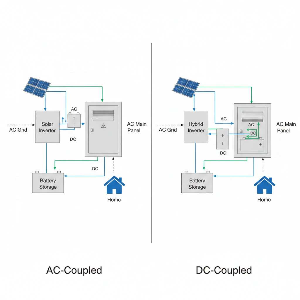
This section provides a high-level overview of each. For a detailed, side-by-side deep dive into the two most common options — AC-coupled and DC-coupled — see our dedicated companion article: AC-Coupled vs DC-Coupled Battery Systems: Which Architecture Is Right for Your Solar Storage?
DC-Coupled — Maximum Efficiency
Solar Panel (DC) → Hybrid Inverter MPPT (DC-DC) → Battery (DC)
                         ↓
                   Inverter Stage (DC-AC) → Home Loads (AC)
                         ↕
                       Grid (AC)
In a DC-coupled system, the solar array and the battery sit on the same DC bus inside the hybrid inverter. Solar energy passes through the MPPT controller and flows directly to the battery with only a DC-to-DC conversion — the most efficient transfer path possible at 97 to 99 percent. When the home needs power, the inverter converts stored DC to AC in a single step.
Core strengths:
- Highest round-trip charging efficiency due to minimal conversion steps
- Lowest system cost — one hybrid inverter serves both PV and battery
- Simplest wiring layout
Key limitations:
- PV and battery share inverter capacity — under heavy simultaneous load, one may throttle the other
- Adding the battery to an existing string-inverter system requires replacing the inverter
- PV string design must match both the inverter MPPT window and the battery voltage range
Best fit: New-build installations where solar and storage are deployed together, and maximum efficiency is the priority.
EWAY’s 48 V / 51.2 V low-voltage battery modules connect directly to the DC battery input of popular hybrid inverters from Deye, Growatt, Goodwe, and others — no additional conversion hardware required.
AC-Coupled — Best for Retrofits
Solar Panel (DC) → String/Micro Inverter (DC-AC) → AC Bus → Home Loads (AC)
                                                      ↕
                                              Battery Inverter (AC-DC) ↔ Battery (DC)
                                                      ↕
                                                    Grid (AC)
In an AC-coupled system, the solar array has its own dedicated inverter, and the battery has a separate battery inverter. Both connect to the home’s AC distribution bus independently. To charge the battery from solar, energy must first be converted from DC to AC by the PV inverter, then from AC back to DC by the battery inverter — two extra conversion steps compared to DC coupling.
Core strengths:
- Does not disturb existing PV systems — simply add a battery and battery inverter alongside
- PV and battery capacities are fully independent and can be expanded separately
- Any existing inverter type (string, micro) can remain in place
- PV array and battery can be physically located in different places
Key limitations:
- Lower charging efficiency (typically 88 to 92 percent round trip) due to multiple DC-AC-DC conversions
- Higher total cost — two inverter units instead of one
- More complex wiring
Best fit: Homes that already have an operational solar system and want to add battery storage without replacing the existing inverter.
📖 For the full efficiency calculations, cost comparison tables, and scenario-based recommendations between AC and DC coupling, read our complete guide:
AC-Coupled vs DC-Coupled Battery Systems →
Hybrid (AC + DC) Coupled — Maximum Flexibility
Solar Panel A (DC) → Hybrid Inverter MPPT → Battery (DC)     [DC path]
                            ↕
                      AC Bus → Home Loads (AC)
                            ↕
                          Grid (AC)
                            ↕
Solar Panel B (DC) → String Inverter (DC-AC)                  [AC path]
A hybrid-coupled architecture combines both topologies in a single system. The hybrid inverter handles a primary PV array and the battery on its DC side, while a second PV array (or a future expansion) feeds through a standard string inverter on the AC side.
Core strengths:
- Captures DC-coupled efficiency for the primary array while allowing AC-coupled expansion
- Most flexible upgrade path — add PV on either the DC or AC side at any time
- Ideal for phased projects where budget or roof space limits initial installation
- Single hybrid inverter manages the full system with one monitoring interface
Key limitations:
- Hybrid inverters carry a price premium over basic string inverters
- System design complexity increases — the installer must consider both DC and AC side constraints
- Firmware compatibility across the hybrid inverter, string inverter, and battery must be verified
Best fit: Homeowners who want to start with a core solar-plus-storage system today and retain the option to expand PV capacity or battery storage in any direction over the following years.
EWAY’s stackable LiFePO4 modules pair naturally with this architecture. Start with a single 10 kWh module on the hybrid inverter’s DC side. Years later, add two more modules and a second PV string on the AC side. The architecture absorbs the growth without a single component replacement.
Off-Grid — Complete Energy Independence
Solar Panel (DC) → Charge Controller / Hybrid Inverter → Battery Bank (DC)
                              ↓
                    Off-Grid Inverter → All Home Loads (AC)
                              ↓
                   Diesel/Propane Generator (backup) → Charger → Battery
An off-grid system has no connection to the utility grid whatsoever. The battery bank is the sole energy buffer, making capacity sizing the most critical design parameter. A backup generator — diesel, propane, or increasingly a large portable solar array — provides a secondary charging source for extended cloudy periods.
Core strengths:
- Total energy independence — no utility bills, no grid outages, no rate changes
- Essential for remote locations with no grid access
- Eliminates all utility fees, demand charges, and connection costs
Key limitations:
- Battery bank must be substantially larger (often two to three times a grid-tied system) to cover nights and low-solar days
- Requires careful load management — occupants cannot draw unlimited power
- Highest initial capital cost
- Backup generator adds maintenance, fuel cost, and noise
Best fit: Remote properties without grid access — farms, islands, mountain cabins — or homeowners philosophically committed to full energy sovereignty.
EWAY’s high-capacity stackable platform (up to 61.44 kWh across six modules) has been deployed in off-grid installations across Queensland, Southeast Asia, and Southern Africa, replacing diesel generators as the primary energy source.
Quick Comparison Table
| Dimension | DC-Coupled | AC-Coupled | Hybrid | Off-Grid |
|---|---|---|---|---|
| Charging efficiency | 97–99 % | 88–92 % | 93–97 % | 93–97 % |
| Retrofit friendliness | Low | Very High | High | N/A |
| Expansion flexibility | Moderate | Very High | Very High | Moderate |
| Typical system cost (10 kWh) | Lower | Higher | Medium-High | Highest |
| Backup capability | Good | Good | Excellent | Full |
| Wiring complexity | Simple | Moderate | Moderate-High | High |
| Best scenario | New build | Add to existing solar | Phased growth | No grid |
This table provides a starting point. The “right” architecture depends on your specific home, your existing equipment, your budget horizon, and your expansion plans. The next section gives you a structured way to make that decision.
How to Choose the Right Architecture — A Decision Framework
Architecture selection can feel overwhelming when four viable options sit on the table. The following five-step decision tree simplifies the process by asking sequential yes-or-no questions. Each answer narrows the field until one or two architectures remain.
Step 1 — Do you already have a solar PV system installed?
Yes → Your existing inverter is the anchor point. If it is a string or microinverter with no battery port, AC-coupled is the path of least resistance — you simply add a battery and a battery inverter without disturbing the PV side. If you are willing to replace the inverter, hybrid becomes available and often worthwhile for the efficiency gain.
No → You are starting from a blank slate. All four architectures are open. Move to Step 2.
Step 2 — Do you have a grid connection?
No → Off-grid is your only option. Design the battery bank for three or more days of autonomy, add a backup generator, and size the PV array to recharge the full bank within one clear-sky day.
Yes → Move to Step 3.
Step 3 — Do you plan to expand the system in the future?
Yes, and the scope is uncertain → Choose hybrid. It accepts additional PV on both the DC and AC sides and additional battery modules in parallel. You will never be boxed in.
No, I want a one-time installation → Move to Step 4.
Step 4 — What is your primary goal?
Maximum energy efficiency and lowest operating cost → DC-coupled. Fewer conversion steps mean more of every solar kilowatt-hour reaches your appliances or battery.
Maximum flexibility and independent scaling of PV and battery → Hybrid. Slightly lower efficiency than pure DC coupling, but far more adaptable.
Step 5 — What is your budget?
Tight budget → DC-coupled delivers the most performance per dollar. One hybrid inverter covers both PV and battery, eliminating the cost of a second inverter unit.
Comfortable budget → Hybrid. The upfront premium buys long-term optionality that typically pays for itself when you expand.
| Decision Path | Recommended Architecture |
|---|---|
| Existing solar + keep inverter | AC-Coupled |
| Existing solar + replace inverter | Hybrid |
| New build + no expansion plans + tight budget | DC-Coupled |
| New build + future expansion likely | Hybrid |
| No grid connection | Off-Grid |
If you are still weighing AC versus DC coupling specifically, our detailed comparison covers efficiency calculations, cost modeling, and scenario-based recommendations: AC-Coupled vs DC-Coupled Battery Systems →
Deep Dive — BMS and EMS: The Invisible Architecture
Most guides stop at boxes and wires. But the true architecture of a modern ESS extends into software and communication layers that are invisible yet absolutely critical. A beautifully wired system with a misconfigured BMS or a silent EMS is a system that underperforms — or shuts down entirely.
This section pulls back the curtain on the two intelligence layers that separate a functional installation from an optimized one.
BMS at the Cell Level — More Than a Safety Net
We introduced BMS functions earlier. Here we go deeper into how a high-quality BMS — the kind required by IEC 62619 — actively shapes system behavior.
Active versus passive balancing. Most budget BMS boards use passive balancing: they bleed excess charge from high cells through resistors, wasting energy as heat. High-performance BMS units — including those in EWAY battery modules — use active balancing, which shuttles charge from high cells to low cells through an inductor or capacitor. The difference matters over thousands of cycles. Active balancing maintains tighter cell voltage uniformity, which preserves usable capacity deeper into the battery’s life.
IEC 62619 compliance in practice. When people see “IEC 62619 certified” on a spec sheet, they may not realize the rigor behind that mark. The standard requires the BMS to demonstrate:
- Automatic disconnection during external short circuit within milliseconds
- Prevention of any cell exceeding the manufacturer’s maximum voltage during an overcharge fault
- Safe behavior when forced into deep discharge below the minimum voltage threshold
- No fire and no explosion when the entire pack is held at 130 °C for thermal abuse testing
- Structural integrity after mechanical shock and vibration sequences simulating transport and seismic events
Every EWAY residential battery module has passed every one of these tests under third-party laboratory conditions. The test reports are available for download.
EWAY BMS technical profile:
| Parameter | Specification |
|---|---|
| Balancing method | Active, ≥100 mA transfer current |
| Overcharge cutoff | 3.65 V per cell |
| Overdischarge cutoff | 2.50 V per cell |
| Charge temperature range | 0 °C to 55 °C |
| Discharge temperature range | −20 °C to 60 °C |
| Communication | CAN 2.0B and RS485 (Modbus RTU) |
| Certifications | IEC 62619 · CE (RED + EMC) · UN 38.3 |
EMS at the System Level — From Rule-Based to AI-Driven
The EMS orchestrates every energy transaction in your home. Its quality determines how much money the battery actually saves you — two identical hardware installations with different EMS strategies can produce ROI differences of 20 percent or more.
Rule-based EMS is the current mainstream. The homeowner or installer programs time windows and SOC thresholds: “Charge from solar 9 AM to 3 PM. Discharge to home 5 PM to 9 PM. Hold at 20 percent minimum for backup.” Simple, reliable, but unable to adapt to changing conditions.
Weather-aware EMS adds a layer. By pulling forecast data, it can pre-charge the battery from the grid at off-peak rates if tomorrow will be overcast — rather than arriving at sunset with a half-empty battery and buying peak-rate power.
AI-optimized EMS is the emerging frontier. Machine learning models trained on weeks of household consumption data, local weather patterns, and dynamic utility rate signals can continuously adjust the dispatch strategy. Early adopters report 10 to 15 percent additional savings compared to static rule-based setups.
Regardless of intelligence level, every EMS depends on reliable data. And that data flows through one critical link: the communication bus between BMS and inverter.
The Communication Chain — Where Most Problems Hide
Discussion forums are filled with frustrated homeowners reporting the same symptoms: the battery suddenly stops charging, the inverter throws a “battery communication lost” error, or the app shows zero percent SOC when the battery is actually half full. In the vast majority of cases, the root cause is not a hardware defect. It is a communication misconfiguration.
EWAY batteries support two industry-standard protocols:
CAN Bus (CAN 2.0B). The fastest and most reliable option for real-time BMS data. CAN uses differential signaling on a twisted pair cable, making it highly resistant to electromagnetic interference. Most hybrid inverters from Deye, Growatt, Goodwe, and SolarEdge prefer CAN for battery communication.
RS485 (Modbus RTU). A universal serial standard supported by virtually every inverter on the market. Slightly slower than CAN but simpler to configure. Victron, Schneider, and many Chinese-brand inverters use RS485 as their primary battery port.
Common communication faults and fixes:
| Symptom | Likely Cause | Fix |
|---|---|---|
| “Battery not found” on inverter display | Baud rate mismatch (e.g., BMS at 500 kbps, inverter expecting 250 kbps) | Match baud rate in inverter settings to EWAY default (see manual) |
| Intermittent disconnections | Cable shielding not grounded at one end | Ground the shield at the inverter end only — do not ground both ends |
| SOC reads 0 % despite battery being charged | Protocol ID / battery brand selection wrong in inverter menu | Select the correct battery protocol profile (EWAY provides profile codes for each inverter brand) |
| CAN communication works but data is stale | Termination resistor missing on the last device in the CAN chain | Enable the 120 Ω termination resistor on the final battery module |
EWAY ships a brand-specific quick-start card with every battery module, listing the exact DIP switch positions, protocol IDs, and inverter menu settings for the twenty most common inverter models. This eliminates the guesswork that causes most field communication issues.
System Sizing — Designing Your ESS Architecture from the Numbers
Architecture selection tells you how the system connects. Sizing tells you how big each piece needs to be. Get the architecture right but the sizing wrong, and you end up with a battery that is too small to see you through the night — or too large to ever pay for itself.
Step 1 — Calculate Your Daily Energy Consumption
Pull your electricity bills for the past twelve months. Add up total annual consumption and divide by 365. This gives your average daily use in kilowatt-hours.
If bills are unavailable, use these benchmarks:
| Household Profile | Typical Daily Use (kWh) | Suggested Battery Range (kWh) |
|---|---|---|
| Small apartment, 1–2 occupants | 8–15 | 5–10 |
| Medium home, 3–4 occupants | 15–25 | 10–20 |
| Large home, EV, heat pump | 25–40 | 20–30+ |
Step 2 — Define Your Backup Requirements
Decide whether you need whole-home backup (every circuit protected) or essential-load backup (only critical circuits). Whole-home backup requires a larger battery and inverter; essential-load backup is more economical and sufficient for most families.
Use this formula:
Required capacity (kWh) = Critical load power (kW) × Backup duration (hours)
                          ÷ Depth of discharge (DoD) ÷ Inverter efficiency
Example: You want to keep 2 kW of critical loads running for 10 hours during an outage.
2 kW × 10 h ÷ 0.90 DoD ÷ 0.96 efficiency = 23.1 kWhAn EWAY stackable system with three 10.24 kWh modules — totaling 30.72 kWh — covers this requirement with comfortable headroom.
Step 3 — Match PV Array Size to Battery Capacity
The PV array must produce enough energy each day to cover household loads and recharge the battery. A useful rule of thumb:
- Self-consumption focus: PV capacity (kW) to battery capacity (kWh) ratio of roughly 1:2 to 1:3
- Full backup focus: Ratio of roughly 1:3 to 1:4
For a 20 kWh battery aiming at self-consumption, a 7–10 kW PV array is a reasonable starting point. Adjust upward for high-latitude locations with fewer peak sun hours.
Step 4 — Let the Numbers Confirm Your Architecture
System size often validates — or overrides — your initial architecture preference:
| System Size | Natural Architecture Fit | Rationale |
|---|---|---|
| Small (5–10 kWh) | DC-Coupled | One hybrid inverter handles everything at lowest cost |
| Medium (10–20 kWh) | Hybrid | Balances efficiency and expansion headroom |
| Large (20+ kWh) | Hybrid or multi-inverter parallel | May exceed single inverter battery port capacity; parallel inverters distribute the load |
If your sizing calculation lands in the “large” category, verify that your chosen hybrid inverter supports the total battery capacity. Most 5 kW hybrid inverters accept 10 to 20 kWh on the DC battery port. Beyond that, you may need to parallel a second inverter or move to a higher-rated unit. EWAY’s compatibility database lists maximum supported module counts for each inverter model.
Wiring and Installation Best Practices
Clean architecture on paper means nothing if the physical installation introduces safety risks, voltage drops, or communication noise. This section covers the essentials that separate a professional installation from a problematic one.
Standard Wiring Configurations
Wall-mounted single-module layout. The most common residential configuration. A single EWAY wall-mounted battery connects to the hybrid inverter via DC power cables (positive and negative) and a communication cable (CAN or RS485). A DC breaker or fuse sits between the battery and inverter. Grounding conductors bond the battery chassis to the home’s grounding electrode system.
Stacked multi-module layout. For higher capacities, EWAY modules stack vertically on a base bracket. Modules connect to each other in parallel through integrated bus bars — positive to positive, negative to negative. The communication cables daisy-chain from module to module using CAN Bus, with a 120 Ω termination resistor enabled on the last module in the chain. A single combined DC cable run connects the stack to the hybrid inverter.
EASYWAY× Inverter Brand Quick-Start Reference
Installer feedback — particularly from online communities — consistently highlights protocol configuration as the number-one pain point. To address this, EASYWAY provides brand-specific setup parameters:
| Inverter Brand | Recommended Protocol | Key Setting |
|---|---|---|
| Deye SUN series | CAN | Battery type → “Lithium,” Protocol → “CAN,” Baud → 500k |
| Growatt SPF/SPH | CAN | Battery → “LI,” CAN address → per EWAY quick-start card |
| Victron MultiPlus-II | CAN (via Cerbo GX) | DVCC enabled, EASYWAY listed as compatible in Victron database |
| Goodwe ET/BT | CAN | Battery brand → “EASYWAY ” (if listed) or “General CAN” protocol |
| SolarEdge Home Hub | RS485 (Modbus) | Third-party battery integration enabled in SetApp |
Each EWAY shipment includes a printed quick-start card and a QR code linking to a video walkthrough for the specific inverter brand ordered. The goal is zero communication errors on first power-up.
Installation Safety Checklist
Before energizing any residential ESS, verify:
- [1] Mounting location is well-ventilated with ambient temperature between 0 °C and 45 °C
- [2] Battery is at least one meter from combustible materials
- [3] Equipment grounding conductor connects battery chassis to grounding electrode
- [4] DC breaker or fuse between battery and inverter is correctly rated (check EASYWAY spec sheet for recommended amperage)
- [5] Communication cable is shielded twisted pair with shield grounded at one end only
- [6] All cable polarities verified with multimeter before closing DC breaker
- [7] Inverter firmware updated to the latest version supporting EASYWAY battery protocol
Safety Standards and Compliance
Safety is not a feature. It is a prerequisite. This section explains the certifications that matter for residential ESS, what they actually test, and how EWAY’s portfolio maps to each.
Certifications That Matter
| Certification | Full Name | What It Covers | EWAY Status |
|---|---|---|---|
| CE | Conformité Européenne | European market access — RED (electrical safety) + EMC (electromagnetic compatibility) | ✅ Certified |
| IEC 62619 | Secondary lithium cells and batteries for industrial applications | Battery-level safety: short circuit, overcharge, thermal abuse, mechanical shock | ✅ Certified |
| UN 38.3 | Transport of Dangerous Goods — Lithium Batteries | Transportation safety: altitude simulation, thermal shock, vibration, shock, short circuit | ✅ Certified |
| UL 9540 | Energy Storage Systems and Equipment | System-level safety for North American market | 🔄 In progress |
| UL 9540A | Thermal Runaway Fire Propagation Test | Validates that thermal runaway in one cell does not propagate to adjacent cells | 🔄 In progress |
IEC 62619 — What the Tests Actually Involve
IEC 62619 is the most directly relevant safety standard for residential LiFePO4 batteries. It subjects the battery to a series of abuse conditions designed to simulate real-world failure modes:
External short circuit test. The battery terminals are connected through a low-resistance conductor. The BMS must detect the fault and interrupt current before the cells reach dangerous temperatures. EASYWAY batteries disconnect within milliseconds.
Overcharge protection test. The battery is charged at maximum rated current with the upper voltage limit removed. The BMS must autonomously terminate charging before any cell exceeds the safety threshold. This test validates that even if the inverter sends a faulty charge command, the BMS independently prevents harm.
Forced discharge test. The battery is discharged far below its normal minimum voltage. The BMS must open the circuit before cells suffer irreversible damage.
Thermal abuse test. The entire pack is placed in an oven at 130 °C and held for a defined period. The battery must not catch fire, explode, or emit toxic gases. This test is especially relevant for LiFePO4 chemistry, which has a thermal runaway onset near 270 °C — providing a wide safety margin.
Mechanical shock and vibration. The pack is subjected to acceleration pulses and vibration profiles simulating earthquake conditions and rough transport. All electrical connections must remain intact; no leakage is permitted.
EASYWAY test reports are issued by accredited third-party laboratories and are available on request or via the certification download center on our website.
CE Marking — RED and EMC for the European Market
CE marking for energy storage products covers two directives:
Low Voltage Directive (2014/35/EU) ensures the battery and its enclosure do not present electrical shock, fire, or mechanical hazards during normal operation and foreseeable misuse. Testing includes insulation resistance, dielectric strength, fault condition analysis, and enclosure ingress protection.
Electromagnetic Compatibility Directive (2014/30/EU) ensures the battery does not emit electromagnetic interference that could disrupt other household electronics, and that it is immune to external electromagnetic disturbances (e.g., from nearby radio transmitters or power tools). This is particularly important for the CAN Bus and RS485 communication lines, which must function reliably in electrically noisy residential environments.
Regional Compliance Quick Reference
| Region | Required Certification | Recommended |
|---|---|---|
| European Union | CE (RED + EMC) | IEC 62619 |
| United Kingdom | UKCA | IEC 62619, BS EN 62619 |
| United States | UL 9540, UL 1973 | UL 9540A |
| Australia / NZ | IEC 62619, AS/NZS 5139 | CEC Approved Battery List |
| Japan | JIS C 8715-2 | JET certification |
🛡️ EASYWAY Certification Portfolio: CE (LVD + EMC) ✅ · IEC 62619 ✅ · UN 38.3 ✅ · MSDS/SDS ✅
📄 [Download the full certification package →]
Scalability — Why Modular Architecture Pays for Itself
The home you live in today may not match the home you live in three years from now. Energy needs evolve. Electric vehicles add 10 to 15 kWh of daily demand. Heat pumps shift heating load from gas to electricity. New family members increase baseline consumption. Utility rate structures change, making larger batteries more profitable.
A system designed without scalability in mind forces a painful choice when needs grow: either live with inadequate capacity or rip out existing equipment and start over. A modular, stackable architecture eliminates that dilemma.
How Stacking Changes the Architecture
EWAY’s stackable battery system is designed around parallel expansion. Each module is a self-contained unit with its own LiFePO4 cells, its own BMS, and its own communication interface. Adding a module is a mechanical and electrical plug-and-play operation:
- Mount the new module on the stack bracket above or below existing modules
- Connect positive-to-positive and negative-to-negative bus bars
- Daisy-chain the CAN Bus cable from the existing last module to the new module
- Enable the termination resistor on the new last module, disable it on the previous last module
- Power on — the master BMS auto-discovers the new module and reports updated total capacity to the inverter
No inverter reprogramming. No firmware changes. No rewiring of the DC main cable.
EASYWAY Stackable System Specifications:
| Parameter | Value |
|---|---|
| Module capacity options | 5.12 kWh / 10.24 kWh |
| Maximum modules per stack | 6 |
| Maximum system capacity | 61.44 kWh |
| Expansion method | Plug-and-play parallel |
| Inter-module communication | Daisy-chain CAN Bus |
| Compatible inverter brands | 20+ (Deye, Growatt, Victron, Goodwe, SolarEdge, and more) |
| Certifications | CE · IEC 62619 · UN 38.3 |
Architectural Limits of Stacking
Every inverter has a maximum battery port power rating. A 5 kW hybrid inverter may support a maximum of 20 or 30 kWh on its battery input. Exceeding that limit does not damage anything — the inverter simply cannot charge or discharge faster than its rated power.
For systems that need both high capacity and high power (e.g., 40 kWh with 10 kW charge/discharge), the architecture must step up to parallel inverters. Two 5 kW hybrid inverters in parallel provide 10 kW of battery throughput and double the PV input capacity. This is still a hybrid architecture — it just scales horizontally.
Future-Proofing Recommendations
Even if today’s budget only covers 10 kWh, make these choices now to avoid regret later:
- Choose a hybrid inverter — even if you are installing only one PV string and one battery. The hybrid inverter’s DC battery port is your expansion gateway.
- Choose a battery with open-protocol communication — CAN Bus and RS485 ensure the battery can talk to virtually any current or future inverter.
- Reserve physical space — leave wall or floor area for at least two additional battery modules, and install conduit or cable trays that can accommodate future wiring runs.
Cost and ROI Across Architecture Types
Architecture affects not only performance but also economics. The number of inverters, the efficiency of each conversion step, and the total battery capacity needed all vary by topology.
Component Cost Comparison
| Cost Category | DC-Coupled | AC-Coupled | Hybrid | Off-Grid |
|---|---|---|---|---|
| PV array | $$ | $$ | $$ | $$$ |
| Inverter(s) | $ (one hybrid) | $$ (two units) | $$ (one hybrid + optional string) | $$ (off-grid inverter) |
| Battery (10 kWh) | $$$ | $$$ | $$$ | $$$$ (larger bank) |
| BoS and installation | $ | $$ | $$ | $$$ |
| Typical total (10 kWh, installed, US) | $8,000–12,000 | $10,000–15,000 | $11,000–16,000 | $15,000–25,000 |
These figures represent fully installed residential systems in the US market as of early 2025. Battery module costs are trending toward $300–$400 per kWh at the system level and are expected to continue declining. As an OEM and ODM manufacturer, EASYWAY offers competitive module pricing to distributors and installers — contact us for volume pricing.
Payback Period by Scenario
| Scenario | Architecture | Estimated Payback |
|---|---|---|
| California, TOU spread $0.25/kWh | DC-Coupled | 5–7 years |
| Germany, feed-in tariff + self-consumption | Hybrid | 6–8 years |
| Australia, high retail rate ($0.35+/kWh AUD) | AC-Coupled (retrofit) | 4–6 years |
| Remote area, replacing diesel generator | Off-Grid | 3–5 years (vs. fuel cost baseline) |
ROI improves further when combined with government incentives. The US federal Investment Tax Credit (ITC) currently covers 30 percent of installed cost. Germany’s KfW program offers low-interest loans. Australia’s state-level battery rebates range from A$3,000 to A$8,000 depending on jurisdiction.
The most overlooked ROI factor is avoided future cost. A modular architecture that accepts additional batteries without hardware replacement saves $2,000 to $5,000 versus a non-expandable system that must be gutted and rebuilt.
Real-World Case Studies
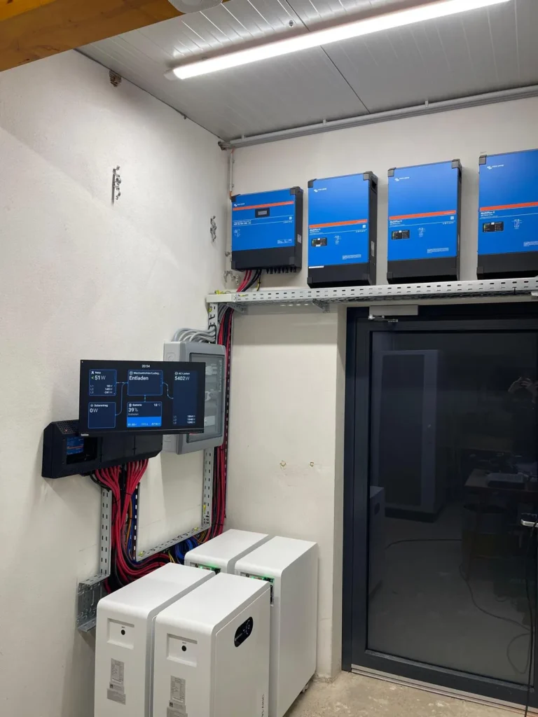
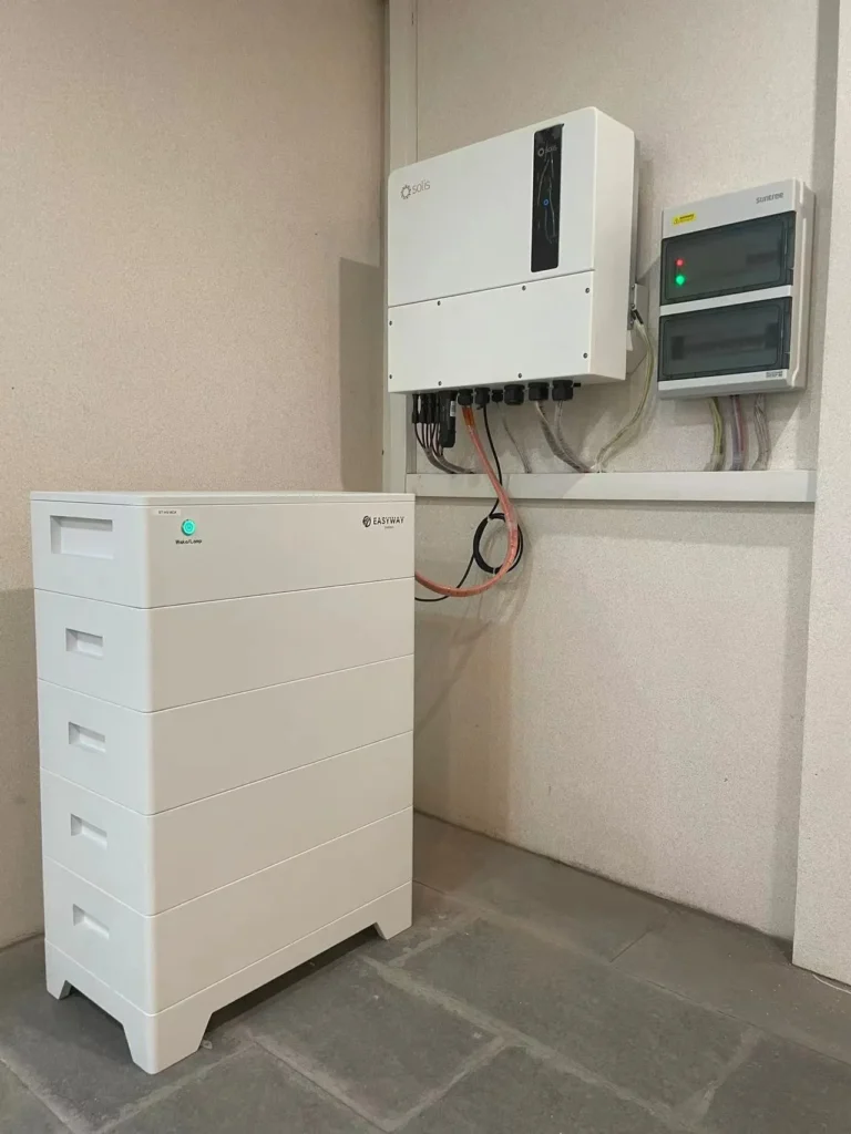
Theory is important. Proof is better. The following three installations demonstrate how different architectures serve different households, all built on EASYWAY LiFePO4 platform.
Frequently Asked Questions
What are the four types of residential ESS system architecture?
The four types are DC-coupled, AC-coupled, hybrid (AC+DC) coupled, and off-grid. DC-coupled connects solar and battery on the DC side of a hybrid inverter for maximum efficiency. AC-coupled links them via separate inverters on the AC bus for retrofit flexibility. Hybrid combines both pathways for maximum scalability. Off-grid eliminates the grid connection entirely for full energy independence.
How do BMS and EMS work together in a home battery system?
The BMS operates at the battery cell level, monitoring voltage, temperature, and current to protect hardware. The EMS operates at the system level, analyzing solar production, home consumption, electricity prices, and battery state of charge to decide optimal energy flow. The BMS feeds real-time data to the EMS via CAN Bus or RS485, enabling the EMS to dispatch energy intelligently without violating battery safety limits.
How many kWh of battery storage do I need for my home?
Start with your average daily electricity consumption. For a grid-tied system focused on self-consumption, size the battery at 50 to 80 percent of daily use. For whole-home backup, multiply critical load power by desired backup hours, then divide by depth of discharge and inverter efficiency. A typical three-to-four-person household uses 15 to 25 kWh daily and benefits from 10 to 20 kWh of storage. EWAY’s stackable modules let you start at 5 kWh and expand to over 60 kWh.
What does IEC 62619 certification mean for a home battery?
IEC 62619 is the international safety standard for secondary lithium batteries used in industrial and residential energy storage applications. It requires passing rigorous abuse tests: external short circuit, overcharge with BMS intervention, forced deep discharge, thermal abuse at 130 °C, mechanical shock, and vibration. A battery certified to IEC 62619 has demonstrated that its BMS can protect against all foreseeable electrical and environmental fault conditions. All EASYWAY residential batteries carry this certification.
Can I add more batteries later without changing my system architecture?
Yes — provided you choose a modular battery system and an inverter that supports additional capacity. EWAY’s stackable modules connect in parallel via plug-and-play bus bars and daisy-chain CAN Bus communication. You can add up to five additional modules (reaching 61.44 kWh) without replacing your inverter, rewiring your distribution panel, or altering your system architecture.
What communication protocol does the battery use to talk to the inverter?
The two dominant protocols are CAN Bus (CAN 2.0B) and RS485 (Modbus RTU). CAN Bus offers faster, more reliable real-time data transfer and is preferred by most hybrid inverter manufacturers. RS485 provides broader compatibility across older or budget inverter models. EWAY batteries support both protocols, ensuring connectivity with over twenty inverter brands.
Is LiFePO4 safer than NMC for residential energy storage?
Yes. LiFePO4 chemistry has a thermal runaway onset temperature of approximately 270 °C, compared to approximately 210 °C for NMC. This 60-degree margin makes LiFePO4 inherently more resistant to thermal events, which is why it has become the preferred chemistry for indoor residential installations. LiFePO4 also contains no cobalt, reducing supply chain risk. All EWAY residential batteries use automotive-grade LiFePO4 cells.
What happens to my ESS during a power outage?
When the grid fails, the automatic transfer switch disconnects your home from the grid within milliseconds and shifts your loads to battery power via the inverter operating in backup mode. If solar panels are producing at the time, they can continue charging the battery through the inverter, extending backup duration well beyond what the battery alone would provide. When grid power returns, the ATS reconnects automatically and the system resumes normal operation.
What is the role of an EMS in residential energy storage?
The Energy Management System is the decision-making brain of your ESS. It collects real-time data — solar production, home consumption, battery SOC, grid electricity price — and determines the optimal action each moment: charge the battery, discharge the battery, export to the grid, or import from the grid. Advanced EMS platforms add weather forecasting, consumption pattern learning, and AI optimization to maximize financial returns.
How much does a residential ESS system cost in 2025?
Fully installed costs vary by architecture and market. A 10 kWh DC-coupled system in the US typically costs $8,000 to $12,000 before incentives. AC-coupled retrofits run $10,000 to $15,000. Off-grid systems with larger battery banks can reach $15,000 to $25,000. Battery module costs are trending toward $300 to $400 per kWh at the system level. As a direct manufacturer, EWAY offers competitive OEM and ODM pricing — distributors and installers are welcome to request a quotation.
Conclusion — Designing Your Ideal Residential ESS Architecture
If this guide has achieved its goal, you now see a residential energy storage system as far more than a battery on a wall. You see an architecture — a network of components, protocols, and strategies that must be designed as a coherent whole.
Five principles should guide every architecture decision:
Architecture before specifications. The way components connect matters more than the individual specs of any single part. A 15 kWh battery in the wrong architecture will underperform a 10 kWh battery in the right one.
Match topology to situation. DC-coupled for new builds seeking efficiency. AC-coupled for retrofits preserving existing equipment. Hybrid for phased growth and maximum optionality. Off-grid for complete energy independence. No single architecture is universally best.
Respect the invisible layers. BMS and EMS are not afterthoughts. They are the intelligence that keeps hardware safe and finances optimized. Choose batteries with open-protocol communication — CAN Bus and RS485 — to ensure interoperability now and in the future.
Build for tomorrow, not just today. Modular, stackable battery systems and hybrid inverters cost marginally more upfront but eliminate expensive redesigns when your energy needs inevitably grow.
Never compromise on safety. CE and IEC 62619 certifications are not marketing badges. They represent physical proof that a battery has survived short circuits, overcharging, extreme heat, and mechanical abuse without catching fire. Insist on them.
EWAY Energy’s LiFePO4 residential battery platform is built on these five principles. Every module is certified to CE (RED + EMC) and IEC 62619. Every module supports CAN Bus and RS485 open-protocol communication with more than twenty inverter brands. Every module is designed for plug-and-play stackable expansion from 5 kWh to over 60 kWh. Whether you are designing a compact DC-coupled system for a city apartment or a high-capacity off-grid installation for a remote farm, the architecture starts with a safe, flexible, scalable battery.
Your next step depends on where you are in the journey:
→ Exploring options? Browse our [Residential Battery Product Line] to see specifications, dimensions, and compatibility lists.
→ Ready to design? Use our [Free ESS Sizing Calculator] to match battery capacity to your consumption profile and architecture type.
→ Need technical support? [Talk to an EASYWAY System Design Engineer] who can review your project requirements and recommend a configuration.
→ Want the full technical package? [Download our Certification and Datasheet Bundle] — including CE, IEC 62619, and UN 38.3 reports.
The architecture you choose today defines the performance, expandability, and safety of your home energy system for the next fifteen years. Choose deliberately.
This article is part of EASYWAY Energy’s Residential Storage Knowledge Center. For related topics, explore:
- AC-Coupled vs DC-Coupled Battery Systems: Which Is Right for Your Solar Storage?
- Home ESS Components Explained (coming soon)
- BMS vs EMS: What Controls Your Home Battery? (coming soon)
- Stackable Battery Scaling Guide (coming soon)
- Battery Safety Standards: CE, IEC 62619, UL 9540 (coming soon)